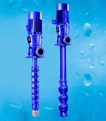
Axial Flow Electropump (ISO 5199)
$0.00Usages:
- Water
- Wastewater
Product features
- Wet-well, single-stage submersible motor pumps
- in discharge tube, with single-entry axial propeller
- in ECB design.
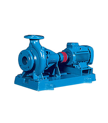
Centrifugal Pumps(ETA Type-ISO5199)
$0.00Usages:
- Fire Fighting
- Water
- Steel complex and mining
- Power Plant
Product features
- Horizontal, long-coupled, single-stage volute
- casing pump in back pull-out design, ratings and
- main dimensions to DIN 24255. Replaceable
- shaft sleeves / shaft protecting sleeves and
- Impeller wear rings.
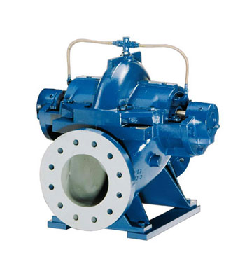
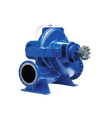
Double Suction Pump (ISO 5199)
$0.00Usages:
- Fire Fighting
- Water
Product features
Design:
- Axially split, single-stage volute casing pump for
- horizontal or vertical installation with double-
- entry radial impeller, connection flanges drilled to DIN, ISO, BS or ANSI standards.
Heavy Slurry pump (ISO 5199)
$0.00Usages:
- Steel complex and mining
Design:
Horizontal, radially split volute casing pump in back pull-out design, with impeller adapted to meet application requirements, single-flow, and single-stage.
Special Features:
- Reinforced, axially adjustable bearing assembly on all pumps.
- Shaft seal: mechanical seal integrated into the casing cover, or gland packing.
- Even cast iron pumps are supplied with pump internals (impeller and wear plate) made of wear-resistant ERN (nickel cast iron).
High Pressure Pump (ISO 5199)
$0.00Usages:
- Fire Fighting
- Water
Product features
- Horizontal or vertical, long or close-coupled,
- multistage centrifugal pump in ring-section design,
- with axial or radial suction nozzle, cast radial impellers.
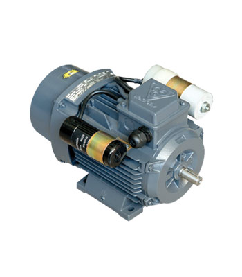
Phase Capacitor Run Electro Motors
$0.00Dimension (Foot mounting – Flange mounting)
Frame No.IEC | T | S | P | N | M | LA | AK | HD | H | C | B | BA | K | KB | AB | A | AA | HA | AC | Z | Q | I | L | E | EH | DH | GA | LK | F | D | FLANGE SYS.IEC 72-1 |
---|---|---|---|---|---|---|---|---|---|---|---|---|---|---|---|---|---|---|---|---|---|---|---|---|---|---|---|---|---|---|---|
56 | 3 | 7 | 120 | 80 | 100 | 8 | 105 | 145 | 56 | 36 | 71 | 19 | 6 | 10 | 112 | 90 | 22 | 10 | 106 | 76 | 55.5 | – | 189 | 20 | – | – | 10.2 | 12 | 3 | 9 | FF100 |
63 | 3 | 10 | 140 | 95 | 115 | 10 | 106 | 158 | 63 | 40 | 80 | 25 | 7 | 10 | 125 | 100 | 25 | 10 | 123 | 76 | 54.5 | – | 214 | 23 | – | – | 12.5 | 12 | 4 | 11 | FF115 |
71 | 3.5 | 10 | 160 | 110 | 130 | 10 | 110 | 175 | 71 | 45 | 90 | 18 | 7 | 10 | 140 | 112 | 28 | 11 | 138 | 76 | 58 | – | 241 | 30 | – | – | 16 | 18 | 5 | 14 | FF130 |
80 | 3.5 | 12 | 200 | 130 | 165 | 12 | 130 | 194 | 80 | 50 | 100 | 25 | 10 | 14 | 160 | 125 | 35 | 11 | 156 | 96 | 68.5 | – | 276 | 40 | – | – | 21.5 | 25 | 6 | 19 | FF165 |
90L | 3.5 | 12 | 200 | 130 | 165 | 12 | 137 | 215 | 90 | 56 | 125 | 30 | 10 | 14 | 182 | 140 | 43.3 | 12 | 175 | 96 | 70.5 | – | 325 | 50 | 19 | M8 | 27 | 32 | 8 | 24 | FF165 |
100L | 4 | 15 | 250 | 180 | 215 | 12 | 145 | 233 | 100 | 63 | 140 | 35 | 12 | 17 | 200 | 160 | 40 | 12 | 194 | 96 | 73.5 | – | 366 | 60 | 22 | M10 | 31 | 40 | 8 | 28 | FF215 |
112M | 4 | 15 | 250 | 180 | 215 | 12 | 155 | 256 | 112 | 70 | 140 | 35 | 12 | 17 | 235 | 190 | 45 | 13 | 217 | 96 | 76.5 | 200 | 384 | 60 | 22 | M10 | 31 | 40 | 8 | 28 | FF215 |
Pump type BB1– According to API 610
$0.00Design:
- Horizontal, axially split, one-and two stage between bearings
- Double suction impeller
- Single or double volute, depending on size
- Diffuser or overflow piece after first stage for two stage execution
- Driving from both sides possible
- Mechanical seals (single, double, tandem)
- Oil lubricated rolling bearings with rotor located by the non drive end for residual hydraulic axial thrust from hydraulically balanced impeller
- Radial as well as axial loads can be also taken by oil lubricated bearings
Pump type OH1-According to API 610
$0.00Usages:
- Oil and Gas
- Petrochemical
- Power Plant
Product features
Design:
- Single-casing, radially split between bearings
- Segmental ring section pumps with tie-rods
- Single suction Impeller
- Sealing between segments by O-rings
- Mechanical shaft seal with single, double or tandem seal
- No limitation for pressures, Spec. gravity and dimensions of casing
- Axial bearing necessary additionally to balancing device
Single Phase Double Capacitor Electro Motors
$0.00Dimension (Foot mounting – Flange mounting)
Frame No.IEC | T | S | P | N | M | LA | AK | HD | H | C | B | BA | K | KB | AB | A | AA | HA | AC | Z | Q | L | E | EH | DH | GA | LK | F | D | FLANGE SYS.IEC 72-1 |
---|---|---|---|---|---|---|---|---|---|---|---|---|---|---|---|---|---|---|---|---|---|---|---|---|---|---|---|---|---|---|
56 | 3 | 7 | 120 | 80 | 100 | 8 | 210 | 145 | 56 | 36 | 71 | 19 | 6 | 10 | 112 | 90 | 22 | 10 | 106 | 76 | 55.5 | – | 20 | – | – | 10.2 | 12 | 3 | 9 | FF100 |
63 | 3 | 10 | 140 | 95 | 115 | 10 | 212 | 158 | 63 | 40 | 80 | 25 | 7 | 10 | 125 | 100 | 25 | 10 | 123 | 76 | 54.5 | – | – | -23 | – | 12.5 | 12 | 4 | 11 | FF115 |
71 | 3.5 | 10 | 160 | 110 | 130 | 10 | 220 | 175 | 71 | 45 | 90 | 18 | 7 | 10 | 140 | 112 | 28 | 11 | 138 | 76 | 58 | 283 | 30 | – | – | 16 | 18 | 5 | 14 | FF130 |
80 | 3.5 | 12 | 200 | 130 | 165 | 12 | 260 | 194 | 80 | 50 | 100 | 25 | 10 | 14 | 160 | 125 | 35 | 11 | 156 | 96 | 68.5 | 331 | 40 | – | – | 21.5 | 25 | 6 | 19 | FF165 |
90L | 3.5 | 12 | 200 | 130 | 165 | 12 | 274 | 215 | 90 | 56 | 125 | 30 | 10 | 14 | 182 | 140 | 43.3 | 12 | 175 | 96 | 70.5 | 380 | 50 | 19 | M8 | 27 | 32 | 8 | 24 | FF165 |
100L | 4 | 15 | 250 | 180 | 215 | 12 | 290 | 233 | 100 | 63 | 140 | 35 | 12 | 17 | 200 | 160 | 40 | 12 | 194 | 96 | 73.5 | 428 | 60 | 22 | M10 | 31 | 40 | 8 | 28 | FF215 |
112M | 4 | 15 | 250 | 180 | 215 | 12 | 300 | 256 | 112 | 70 | 140 | 35 | 12 | 17 | 235 | 190 | 45 | 13 | 217 | 96 | 76.5 | 440 | 60 | 22 | M10 | 31 | 40 | 8 | 28 | FF215 |
Single-Phase Double-Capacitor Electro Motors With Cast-Iron Frame
$0.00Product Specification
Type | Frame size | Output Power | Output Power | Rated Voltage | Speed in rated load | Rated Current | Rated Torque | Efficiency (%) | Power factor | Starting / Rated Current | Starting / Rated Torque | Break down / Rated Torque | Inertia moment | Capacitor Run | Capacitor Run | Capacitor Start | Capacitor Start | Poles |
---|---|---|---|---|---|---|---|---|---|---|---|---|---|---|---|---|---|---|
CRS 100L4B | 100L | 2.2 | 3 | 220 | 1440 | 13.5 | 14.59 | 78 | 0.95 | 4.6 | 1.9 | 1.9 | 0.004613 | 60 | 400 | 230 | 330 | 1 |
Three Phase Electro Motors With Energy Grade Of IE2
$0.00Dimension (Foot mounting)
Frame No.IEC | HD | H | C | B | BA | K | KB | AB | A | AA | Z | HA | AC | Q | I | L | E | EH | DH | GA | LK | F | D |
---|---|---|---|---|---|---|---|---|---|---|---|---|---|---|---|---|---|---|---|---|---|---|---|
80 | 194 | 80 | 50 | 100 | 25 | 10 | 14 | 160 | 125 | 35 | 96 | 11 | 156 | 68.5 | – | 276 | 40 | – | – | 21.5 | 25 | 6 | 19 |
90L | 215 | 90 | 56 | 125 | 30 | 10 | 14 | 182 | 140 | 43.3 | 96 | 12 | 175 | 70.5 | – | 325 | 50 | 19 | M8 | 27 | 32 | 8 | 24 |
100L | 233 | 100 | 63 | 140 | 35 | 12 | 17 | 200 | 160 | 40 | 96 | 12 | 194 | 73.5 | – | 366 | 60 | 22 | M10 | 31 | 40 | 8 | 28 |
112M | 256 | 112 | 70 | 140 | 35 | 12 | 17 | 235 | 190 | 45 | 96 | 13 | 217 | 76.5 | 200 | 384 | 60 | 22 | M10 | 31 | 40 | 8 | 28 |
132M | 291 | 132 | 89 | 178 | 40 | 12 | 17 | 260 | 216 | 44 | 116 | 14 | 255 | 90 | 258 | 486 | 80 | 28 | M12 | 41 | 56 | 10 | 38 |
160L | 340 | 160 | 108 | 254 | 50 | 15 | 21 | 315 | 254 | 64 | 116 | 16 | 303 | 95.5 | 345 | 629 | 110 | 36 | M16 | 45 | 80 | 12 | 42 |